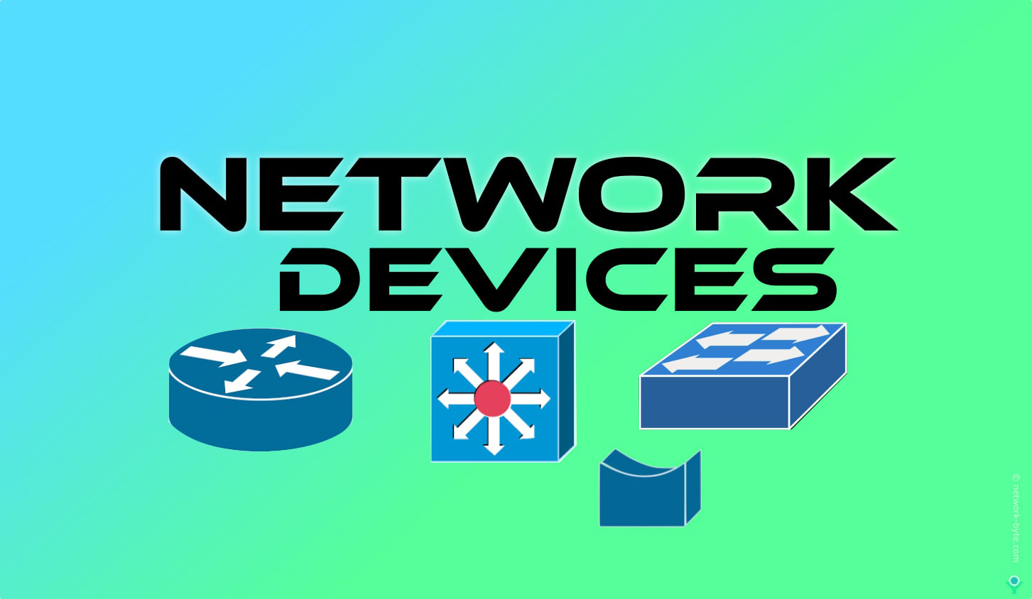
Internetworking is extremely complex that connects different network and LANs through a set of rules and allows host computer to communicate with each other. This type of connections and communication is possible only through the network components and connectors which act as the media for transfer of data. The network devices play major role in interaction and creating a small network .Network device provide the basic functionality and connectivity to a network. Understanding how these networking devices operate and identifying they perform are essential for users. Some of the major network devices are
HUB
It older type of networking device which supports IEEE 10Base-T. The Word Hub derived from the wheel of bicycle which contains spokes connected to the hub in the center. It resembles star topology but internally Bus topology.
It forward data using physical layer standards rather than data-link standards and are therefore considered to be Layer 1 devices can’t store MAC address.
Hub comes in 2,4,6,8 port generally available.
it always Broadcast. It works on half-duplex communication. It has a single collision domain means it has one exit and entry route that increases collision. It has a single collision domain and a single broadcast domain.
In hubs that if two or more devices transmit a signal at the same instant, the electrical signal collides and becomes garbled. The hub repeats all received electrical signals, even if it receives multiple signals at the same time. The hub repeating both electrical signals out toward.
Hubs are generally called as multiport repeaters.
When an electrical signal comes in one hub port, the hub repeats that electrical signal out all other ports (except the incoming port). By doing so, the data reaches all the rest of the nodes connected to the hub, so the data hopefully reaches the correct destination. When data arrive at the same time from two or more device Collisions occur To prevent these collisions, the Ethernet nodes must use half-duplex logic instead of full-duplex logic. Half-duplex logic actually uses an algorithm called carrier sense multiple access with collision detection (CSMA/CD). It can’t eliminate collision permanently.
Hub is of many types with different features/Specifications, Which provide the type of functionality required to build a network. Two Types of Hub are
1.Active Hub
2.Passive Hub
1. Active Hub – It required electricity Power to run. It regenerates or amplifies signals also, It provides the functionality of a repeater, regenerating, and retransmitting signals to all of their devices. It is expensive than passive hubs.
2. Passive Hub – A passive hub simply receives the signal on the input port and broadcasts it on the output port without even repairing it. Passive hubs do not require electrical power to run. Passive hubs do not repeat but merely split signals sent through them. It doesn’t require electricity, It doesn’t amplify the signal
Collision Domain-network segment with two or more devices sharing the same bandwidth(Where there is a chance of collision)
CSMA/CD
Nodes that use half-duplex logic actually use a relatively well-known algorithm called carrier sense multiple access with collision detection (CSMA/CD). The algorithm takes care of the obvious cases but also the cases caused by unfortunate timing. Sense before Send For example, two nodes could check for an incoming frame at the exact same instant, both realize that no other node is sending, and both send their frames at the exact same instant, causing a collision. CSMA/CD covers these cases as well, as follows:
Step 1. A device with a frame to send listens until the Ethernet is not busy.
Step 2. When the Ethernet is not busy, the sender begins sending the frame.
Step 3. The sender listens while sending to discover whether a collision occurs; collisions might be caused by many reasons, including unfortunate timing. If a collision occurs, all currently sending nodes do the following:
- They send a jamming signal that tells all nodes that a collision happened.
- They independently choose a random time to wait before trying again, to avoid unfortunate timing.
- The next attempt starts again at Step 1.
Although most modern LANs do not often use hubs and therefore do not need to use half-duplex.
BRIDGE
A bridge is a physical unit with two ports that connect the network segments together and filters the amount of traffic on each network. A bridge can only be connected to similar network segments because they require the physical address of the device to send the data frames. It is slightly intelligent than HUB. The bridge reduces the amount of traffic on a LAN by dividing it into segments. Bridge inspect incoming traffic and decide whether to forward or reject It check source & Destination MAC Address. It works on the physical and Datalink layer.
Bridge maintains a bridge table that contains a port number and Mac address. It broadcast the first time then unicast.
It has two collision domains, Bridge data unit protocol used to avoid loop.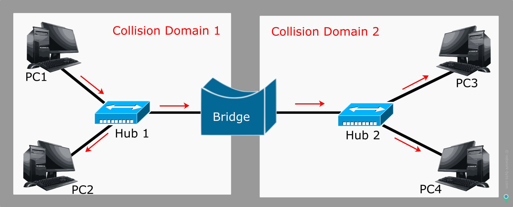
A bridge functions by blocking or forwarding data, based on the destination media access control(MAC) address written into each frame of data. The data packet enters the bridge through one of the port; the bridge then reads the destination address in each packet and decides how to process the data packet. This process is called packet filtering. If the destination address matches the computer on the other network segment, the bridge propagates it through the other port which otherwise discards the data packet. There are Hardware bridge and also a software bridge. There are several types of bridges classified into categories to best suit the networking requirements.
Types of bridges
1. Transparent bridge
2. Translation Bridge
3. Source-route bridge
Transparent Bridge
Transparent bridges are usually implemented in Ethernet networks and very easy to install. It performs the function of blocking or forwarding data on the MAC address. These bridges reduce the impact of broadcast and multicast traffic on a network, Which helps to improve the performance of multicast forwarding.
Translation Bridge
A translation bridge is designed to convert from one networking system to another. It is used for connecting two different networks like Ethernet and token ring networks.
Source-Route Bridge
The source route bridge derives its name from the fact that the entire route of the frame is embedded within the frame. This slows the bridge to make specific decisions about how the frame should be forwarded through the network.
Switch
It is also called Multiport bridge work on layer 2 i.e. data link layer of the OSI reference model. It is an intelligent device it maintains the Content Accessible Memory (CAM) table or MAC (Media Address Control) having ASICs chip. It first broadcast then Unicast and Multicast. It is a full-duplex device. Every port of switch has a separate collision domain. It has one Broadcast Domain default we can increase the broadcast domain by using the concept of VLAN.
A switch would look at the MAC addresses, and even if the switch needed to forward two frames the switch would send one frame and queue the other frame until the first frame was finished.
It has one broadcast domain by Number of Collision domains depends upon the number of ports.
It has lots of ports 8/6/24/48 ports used in the same network.
Types of Switches
UnManageable Switches: No Configuration can be done in unmanaged switch as there is no console port. Ethernet switch is an Ethernet hub. Unmanaged switches use auto negotiated ports to determine parameters such as the data rate and whether to use half-duplex or full-duplex mode.
Manageable Switches: It can configure it has a console port. It provides control over how data travels over the network and who has access to it. Support features like Spanning Tree Protocol(STP), VLAN(Virtual LAN), bandwidth rate limiting, port mirroring, Port Security, etc.
Cisco’s Hierarchical Design Model
Cisco divides the Switches/Router into 3 layers
- Access layer Switches: End devices are connected using this switch.
Cisco series: 1900 & 2900
- Distribution Layer Switches: It is an interface between the layer2 and layer3 domains. Generally, Layer 3 Switch is used in the layer. It receives data from the access layer switch before it is transmitted to the core layer.
Cisco Series: 3000 & 5000
- Core Layer Switches: It is a network backbone having high-speed network devices. It handles large amounts of data.
Cisco Series: 7000,8000 & 10,000
The three-tier hierarchical design maximizes performance, network availability, and the ability to scale the network design.
Small enterprise implements a two-tier hierarchical design where the core and distribution layers are collapsed into one layer is often more practical a “collapsed core”
LAN Switching Technologies or Switching Mode
Three types of Switching Mode
- Store & Forward
- Cut Through
- Fragment Free
Store & Forward
- switch store the entire frame into the switch memory buffers and computes a cyclic redundancy check (CRC) for errors. If a CRC error is found, the frame is discarded.
- It has high level error-free network traffic.
- This Switching method used for distribution-layer switches
- Latency(Delay): High because of entire data frame checked for errors before forwarding
- Error Checking: Yes
Cut Through
- It doesn’t store the entire frame. It Copies only the destination MAC address, which is located in the first 6 bytes of the frame following the preamble.
- A default Switching method for the core-layer Switches
- Latency: Low because read-only destination MAC address and determines the outgoing interface port and forward frame which reduces delay.
- Error Checking: No, Frames with and without errors are forwarded in cut-through switching operations.
Fragment Free
- It is also referred to as runtless switching or modified/Hybrid Cut-Through and store-and-forward switching
- It stores the first 64 bytes of the frame before forwarding. The reason fragment-free switching stores only the first 64 bytes of the frame is that most network errors and collisions occur during the first 64 bytes of a frame.
- A default Switching method for access-layer switches
- Latency: Medium
- Error Checking: On 64 byte of Frame
POE switch
A network switch that supplies power over ethernet cable.Modern devices like IP phone, Wireless Access Points.
IP Camera support POE. It is available in both Managed and Unmanaged versions based on requirements it can be used.
Avaliable in 8, 12, 24, 48 ports.
L3 Switch
Often referred to as a multilayer Switch. Faster-Switching speed than the layer-2 Switch.avalible in 24,48 ports.
It has combined the functionality of a switch and a router.
Used for Virtual LANs, It has multiple broadcast domains.
Layer 3 Switch will typically not possess the WAN ports.
Router
It is an internetworking device used to communicate between two different networks, also called Layer 3 device WAN Device. It Uses IP address and Maintains routing table, Data transfer in the form of packets.
In the router, every port has its own broadcast domain.
Router doesn’t broadcast
Router Ports are divided into three categories
- LAN Port: This port used to connect network switch in the LAN, It is the Gateway for the LAN network.LAN port is Ethernet, FastEthernet, GigabitEthernet.
- WAN Port: This port connected to other routers on the network, or connected to the internet.
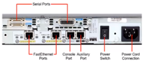
- Admin Port: Router is configured using this port. Console and Auxiliary Console port under this category.
Router Come in Two variance
Fixed Router – All port are integrated on the motherboard (no slot), can’t add, and remove the interface.
Modular Router – Have Slots where you can add or remove cards. Distribution and core layer router are examples of modular Router.
Routing is a process performed by router Selecting an optimal path for traffic in a network or between or across multiple networks. It is done by static or dynamic routing.
NIC
Network interface card, the NIC is also referred to as an Ethernet card or network adapter.
It is used in computers having RJ-45 port used to connect computers in-network or the internet.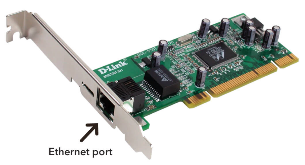
Wireless NIC also available for wireless connection. In a laptop, the network card is integrated into the motherboard. It is both a physical and data link layer device. Every NIC has a 48-bit unique serial number called a MAC address or Physical Address which is stored in ROM carried on the card.
Media Converter
A media converter designed to convert 1000BASE-LX/LH fiber to 1000Base-T copper media or vice versa. It designed for use with single-mode fiber cable utilizing the SC-Type connector. It supports longwave (LX) laser specification at a full wire-speed forwarding rate. It works at 1310nm on both transmitting and receiving data.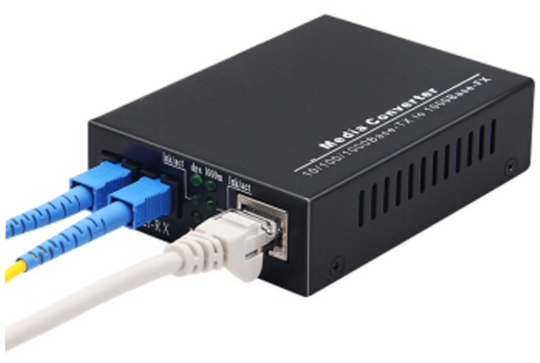
It is essential to have the fiber optic connectivity if the distance between two network devices is greater than the copper cabling’s transmission distance.
A media converter offers fiber-to-fiber conversion as well, from the multi-mode fiber into a single-mode fiber. It also converts a dual fiber link to single fiber with the help of bi-directional (BIDI) data flow.


