Open Systems Interconnection abbreviated as OSI. It has been developed by ISO – “International Organization of Standardization”, in the year 1984. The OSI Reference Model is based on a proposal developed by the International Standards Organization (ISO).The model is called ISO OSI(Open Systems Interconnection) Reference Model because it deals with connecting open systems for communication with other system. It provides a set of general guidelines for data communications systems and also gives a standard way to describe the interaction between the various layers of data communication systems. This model is the best known and the most commonly used to describe networking environments.
The OSI model is an architecture which divides network communication into seven layers. Each layer covers different network activities, Equipment, or protocols and has its own functions. A new layer is created when different functions are introduced. Each Layer should have its own protocols defined.
The Purpose of the OSI Model
- It breaks the network communication into simpler parts that are easier to develop.
- Troubleshooting is easier by separating functions into different layers.
- It prevents the changes in one layer from affecting the other Layers,
- It allows you to compare established relationships on various layers.
The 7 Layers of the OSI Model
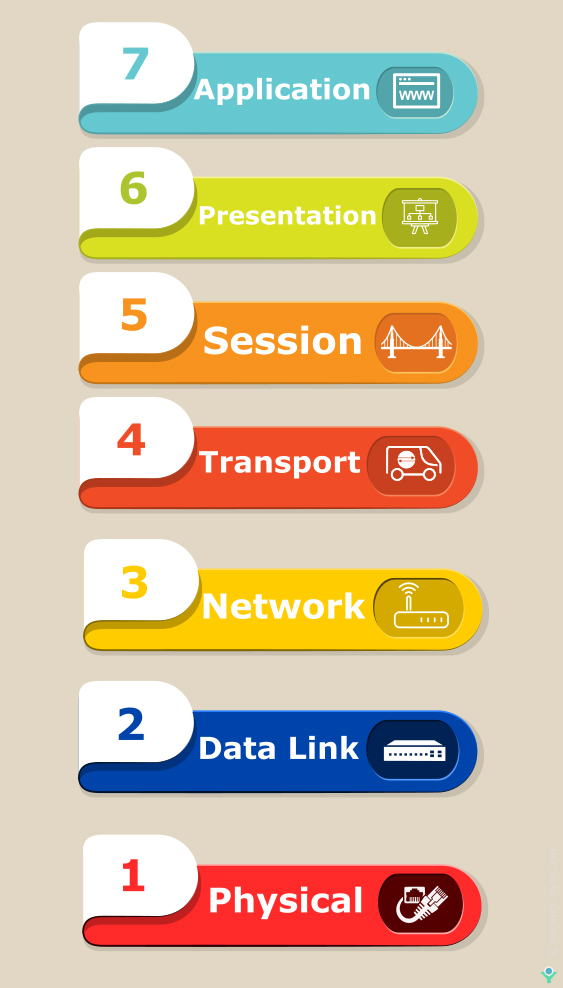
The Open System Interconnect (OSI) model is a Layered approach to networking. It has Seven layers as illustrates in the below image. All these 7 layers work collaboratively to transmit the data from one person to another across the globe.

Remembering the OSI Model 7 layers – 7 mnemonic tricks
An easy way to memorize the Seven Layers
Here are a few sentences to help remember them in order. The beginning letter of each word corresponds to a layer of the OSI model.
From Application to Physical (top-down):
All People Seem To Need Data Processing
A Penguin Said That Nobody Drinks Pepsi
All Pros Search Top Notch Donut Places
A Priest Saw Two Nuns Doing Pushups
From Physical to Application (bottom-up):
Please Do Not Throw Sausage Pizza Away
Pete Doesn’t Need To Sell Pickles Anymore
Pew! Dead Ninja Turtles Smell Particularly Awful
The seven layers of the OSI model can be defined as follows, from top to bottom
Layer 7: Application Layer
The application layer is the entry point that programs use to access the OSI model a utilize network resources. It is responsible for interacting with the actual user application and is responsible for providing application services such as file transfer, e-mail, and network services.
The application layer interacts with the application software and represents the service that supports user application and establishes a user interface to the network services. This layer is usually made available by using an Application Programmer Interface (API) Like Browsers, Messenger-skype, Office 365, etc.

Application Layer is also called as Desktop Layer
Protocols in Application Layer
Common application layer protocols include File Transfer Protocol (FTP), Simple Mail Transfer Protocol (SMTP) and Domain Name System (DNS), POP version 3 (POP3), Simple Network Management Protocol( SNMP), Dynamic Host Configuration Protocol (DHCP), Hypertext Transfer Protocol (HTTP), Hypertext Transfer Protocol Secure (HTTPS), Secure Shell (SSH), teletype network (Telnet),
Layer 6: Presentation Layer
The presentation layer is primarily responsible for preparing data so that it can be used by the application layer. It gives the standard format for transmitting information across various. systems, so, that the data can be understood regardless of the type of systems involved.

It can be viewed as the translator for the network that why it is sometimes is also called the Translation layer. It is responsible for protocol conversion, character conversion, also handles the data encryption and compression and expanding graphics commands.
Presentation layer is also called the Translation layer
Major functions of the Presentation layer are:
- Data Conversion: The sending device can convert text or data into general format ASCII for transmission over a network. the receiving computer converts this format(ASCII) to a format required by the destination application.
- Data Compression: Reduces the number of bits that need to be transmitted on the network
- Data Encryption: Data is converted into encoded form, which cannot be read by unauthorized persons.
- The presentation layer has some of the graphical image formats and visual image representation like TIFF(Tagged Image File Format), a standard graphics format for high-resolution, bitmapped images, and JPEG Photo standard.MPEG(Moving Picture Experts Group) standard for the compression and coding of motion video.
Layer 5: Session Layer
The session layer primarily starts at the beginning and end of a transmission. At the beginning of the transmission, it makes known its intent to transmit. At the end of the transmission, the Session layer determines the successful transmission. The time between when the communication is opened and closed is known as the session.

The session layer enables applications running at two workstations to direct their communications into a single session. The request and responses between the application are synchronized with the help of protocol that is added in this layer.
Important function of the Session Layer:
- Session establishment, maintenance and ends a session.
- It enables two systems for Dialog Controller
- Synchronization which allows the process to add checkpoints
Layer 4: Transport Layer
Transport Layer is responsible for end-to-end communication between the two devices. This includes taking data from the upper layer i.e session layer and breaking it up into chunks called segments before sending it to the Network layer. The transport layer on the receiving device is responsible for integrating the segments into data so the upper layer i.e session layer can consume.

The transport layer ensures that the messages are delivered error-free, in sequence, and with no losses or duplications. The transport layer decides the types of service to be provided to the session layer and establishes connections across the network. Some of the protocols in this layer perform error recovery and control, ensuring that data transferred over the network is received properly.
Transport layer Protocol is generally categorized into
- Connection-oriented
- Connectionless Protocols
1. Connection-oriented
The connection-oriented communication is a process that involves establishing a connection between the two hosts. It transmits the data through the devices at the endpoints which use protocols to establish a connection before sending the data. Transmission Control Protocol (TCP) is a connection-oriented protocol.
The four-step in connection-oriented communication are as follows
- It established a connection between the sending and receiving station
- The two stations notify their operating system that the connection is about to start. (Synchronization) the notification message. The sender will always be notified of the data packets’ failed delivery.
- When the connection between the two devices is complete, the transfer of information begins.
- It sends the data packet to the destination station and lets the other end of the station know the data is receiving i.e Acknowledgement.
- The destination station then sends the data packet back to the source to let the source know that it received the notification message. The sender will always be notified of data packets failed delivery.
- Two devices communicate with each other and ensure that packets are delivered error-free, in sequence with no losses or duplications.
2. ConnectionLess Protocols
In connectionless communication, no initial connection is established between the two endpoints. The device transmits the data from one end to the other end without ensuring that the recipient is prepared to receive the data Internet Protocol (IP) and User Datagram Protocol (UDP)are connectionless protocol. Datagrams provide a connectionless communication service across a packet-switched network.
Functions of the Transport layer
The transport layer has the capacity to accept relatively large messages, but there are strict message size limits forced by the network layer. Consequently, the transport layer must break up the messages into segment units, or frames. Therefore, this layer has a simple method of controlling the excessive amount of data to the other end of the station known as flow control.
Flow Control
Flow control is a method of controlling the rate at which the device sends data. Depending on the particular protocol, the sending and receiving device participate in this process of flow control. The flow control has three standard flavors. They are:
- Buffering
- Congestion
- NotificationWindowing
1. Buffering
Buffering is used in flow control. The input buffer usually can hold enough data packet, but sometimes the data flow at a faster rate than the receiving device can process it. Therefore, buffer overflows and data will be lost. The flow control process helps to prevent buffer overflow by signaling the sending device to stop the transmission allowing the receiving device to empty its buffer before continuing to send the data.
2. Congestion Notification
This is a signaling technique used by data transmission systems in order to indicate the status of the network congestion. Devices that are communicating data across a network rely on congestion notification to decide when to send or delay the transmission of data packets
3. Windowing
Windowing is a technique used to deliver the data packets to the recipient in the same order in which they were transmitted to have a consistent, connection-oriented data transfer. The protocol tends to fail if any data packets are lost, damaged, duplicated, or received in a different order. Therefore, a recipient acknowledge is necessary for the receipt before the next packet of data is sent.
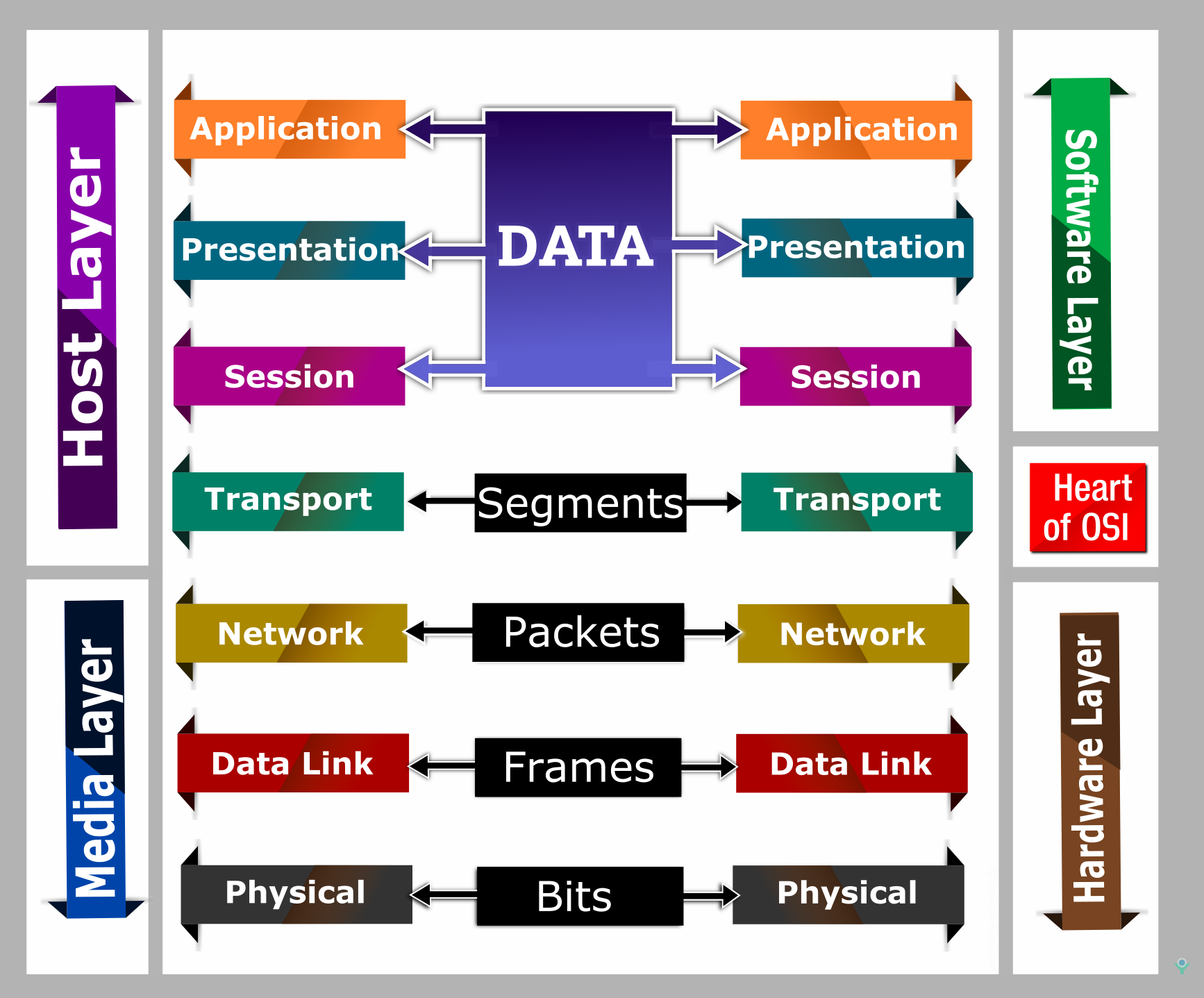
The data in the transport layer is referred to as Segments
Layer 3: Network Layer
The network layer is responsible for facilitating data transfer between two different networks –Host to Host Delivery (Source to Destination Delivery). Network layer added headers containing the logical address of the device. The network layer provides functional and procedural functional and procedural means of transferring data from source to destination over one or more networks. If the two devices communicating are on the same network, then the network layer is unnecessary.

The main device which operates in this layer is a router. Router Provides the routing services for internetwork and records different networks and records different networks and identifies the best path to send the data.
Two important aspects required to send the data from one device to another are
1.Logical address related source and destination.
2.Path through which the data has to be sent to reach the destination
The function of Network Layer
1. Logical Addressing
Network Layer is also responsible for logical addressing. It is also known as network addressing or Layer 3 addressing in the OSI model. Example: Internet Protocol (IP) addressing like 192.168.3.5. Logical addressing is very essential for every device in a network. The devices that operate on this layer are Layer 3 Switches and routers.
2. Routing
The main function of the network layer is to move the data packets through a series of the device in a network. Devices and software at the network layer do routing and it has the basic function to minimize the overall delay of the network. Its main functions include handling incoming packet from several sources to determine their final destination. Network layer encapsulates the messages received from the higher layers by placing network layer header into the datagram(Datagram Encapsulation)
3. Fragmentation
The network layer has to send a message to the data link layer for transmission. But the data link layer has a limit on the length that can be sent from the network layer. If the data packet is very long that has to be sent from the network layer, Then the network layer breaks the data packet into pieces and sends each piece to the data link layer.
4. Error Handling
The network layer also includes error detection and recovery. Special protocols are used at the network layer to allow devices that are logically connected and which also allow exchanging information about the status of hosts on the network or the devices.
Layer 2: Data Link Layer
The data link layer is responsible for the node to node delivery of the message. The data link layer facilitates data transfer between two devices on the SAME network. The data link layer provides a system through which network devices can share the communication channel. This Function is called media-access control (MAC). It also provides an error-free transfer of data frames from one node to another over the physical layer.

Bridges and switches operate at this layer.
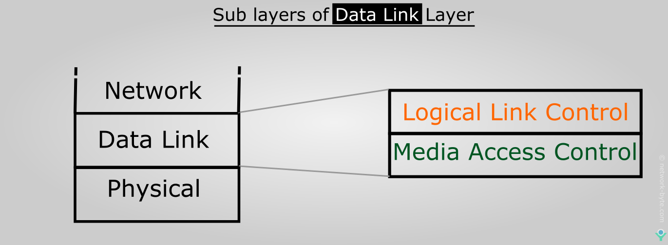
The Data Link Layer is mainly divided into two sub-layers:
- Logical Link Layer
- Media Access Layer

1. Logical Link Layer
The Logical link layer manages the communication between devices over a single link of a network and enables multiple higher-layer protocols to shares a single physical data link- Multiplexing.
2. Media Access Layer
The media access layer or Media Access Control (MAC) manages protocol access to the physical network medium and determines the hardware addresses.
Data Link layer mainly deals with the following aspects:
1.Arbitration
2.Physical Addressing
3.Error detection
4.Data Framing
1. Arbitration
Arbitration is the method to access a single data channel when multiple hosts are using simultaneously. In this method, only one device can send the electrical signal at a time. Any two-device attempts to access the medium at the same time, then the signals from each device will interface causing a collision.
2. Physical Addressing
All network devices must have a physical address i.e MAC Address. The physical address is designed to uniquely identify the devices. It is the required component to transfer the data packets from one end to the other end of the device, specified with the appropriate physical address.
3. Error detection
The data link layer determines the error problems which occur during the transmission data. Introducing a trailer called FCS, which detects the error before it sends the data packets to the remote machine, It does FCS(Frame Check Sequence)uses a Cyclic Redundancy Check (CRC) is often used to allow the station receiving data to detect if it was received correctly.
4. Data framing
The data link layer of both the machines must be using the same frame types so that the data packets will recognize the actual data contents.
Layer 1: Physical Layer
The Physical Layer is the lowest layer of the OSI model and is concerned with the transmission and reception of the unstructured raw bit stream over a physical medium. It describes the Electrical/Optical, Mechanical, and functional interface to the physical medium, and carries the signals for all of the higher layers. It also provides the electromechanical interface through which data moves among devices on the network.

The Physical layer is the most basic network layer, providing only the means of transmitting raw bits.
Some of the functions of the physical layer involve.
- Modification of the data into a simple digital signal pattern as ones and zeros.
- Transmission of raw bitstream over a physical cable
- Conversion of digital data and signals to transmit over the network.
- Communication resources are effectively shared among multiple users.
Repeaters and Hubs operate at physical layer
Communication in an OSI Reference Model
The OSI reference model shows the communication between layers and the data transmission between the two systems. It is divided into upper three layers and lower four layers. The upper three layers of the OSI model deal with the application issues which require access to a resource on the network and usually are implemented only in software. The Lower four layers Provide the basic communication between any two systems in the network. The application layer is the highest layer, closest to the end-user. The lower layers of the OSI model mainly deals with data transport issues.

OSI model is used as a reference not implemented on the Internet, TCP/IP is the standard of networking.
Check This Article Also


