A cable is a device that contains a number of signal conductors usually in the form of separate wires. It is the medium through which information usually moves from one system to another through the network. There are several media types of cables, which are commonly used with the Local Area network. In some cases, a network utilizes only one type of cable, Whereas other network uses a variety of cable types. The types of cable chosen for a network is related to the network’s topology, protocol, and size. Different types of cable are used in modern computer networks. The network connection for a system is important to transfer data from one system to another through the network medium via cable. The cable is relatively popular for a wide variety of communication systems like television, telephone, computer network.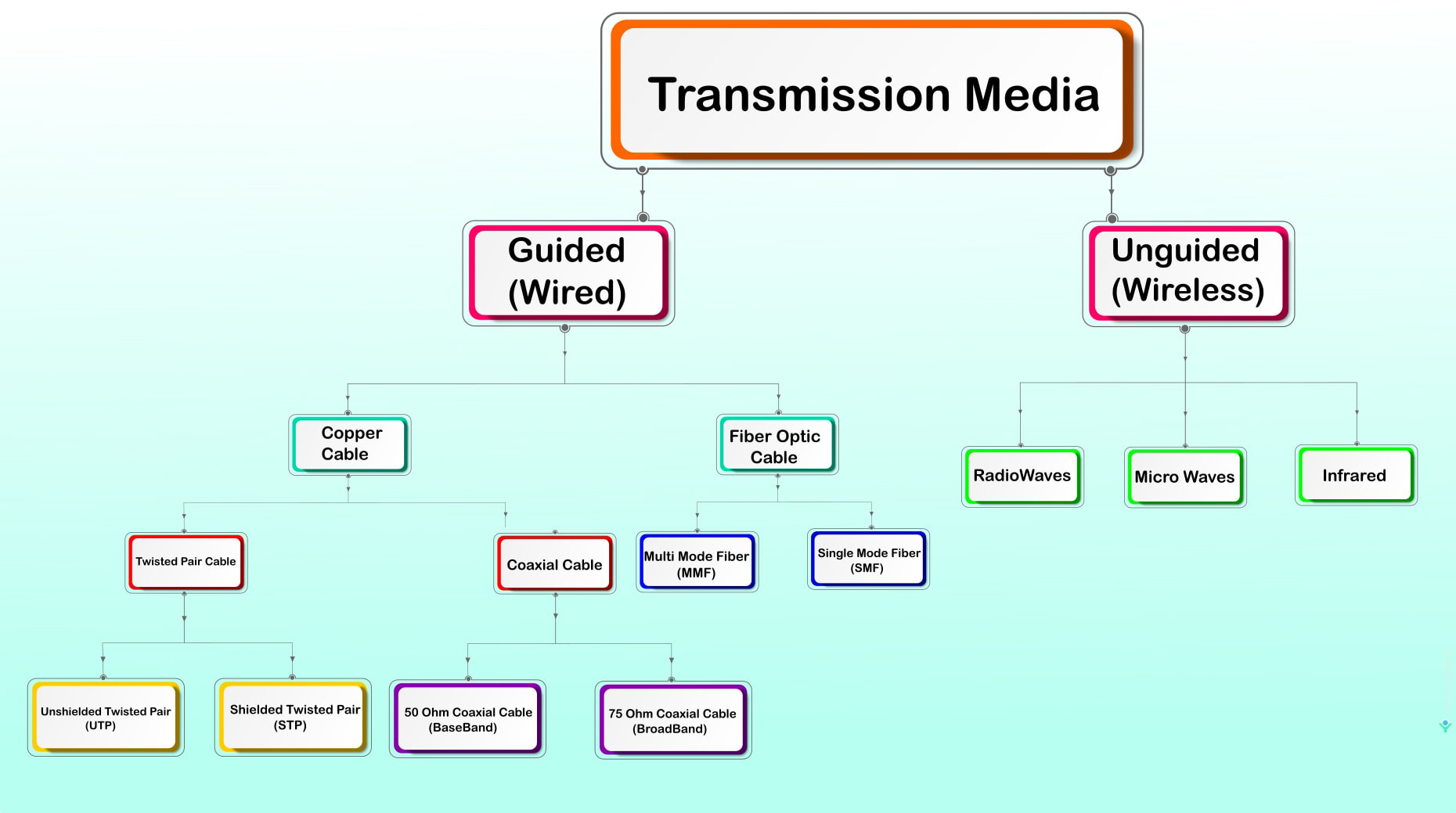
Guided transmission media means the data signals are guided along the path like a cabling system.
Types of guided Media
Coaxial Cable
A coax cable or coaxial cable acts as a high-frequency transmission cable at low loss. It contains a single solid-copper core. Coaxial cable is used to pass radio frequency (RF) signals in the form of a transverse electromagnetic wave. it consists of an inner round copper conductor with layers of insulator and shielding to prevent electromagnetic interference.
Coaxial Cable is made up of four Layer
- copper Core
- Dielectric Shielding
- Wire Mesh Outer
- Insulator Jacket
The coaxial cable transmits information in two modes: Baseband mode and Broadband mode. There are two types coaxial cables based on Impedance: 75 Ohm Coaxial Cable and 50 Ohm coaxial Cable
Coaxial cables use RG ratings to distinguish between the different kinds of cables.”RG” stands for “radio guide” and references the capacity of the cable. Dozens of Coaxial cables with various RG standard based on application and their manufacturing.
50 Ohm Coaxial Cable
50 Ohm Coaxial Cable used in base band (dedicated cable bandwidth) Transmission for two way communication example Thicknet and Thinnet, Wireless antenna ,GPS Antenna, Cellular systems.
RG-58 is 50-ohm coaxial cable and is typically used for radio communications and thin Ethernet (10base2) networks.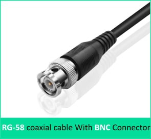
BNC (Bayonet Neill-Concelman) RF connectors make it easy to connect coaxial cables with radio-frequency equipment like radios,TVs and telecommunication Equipment.
The amount of ohms measures electrical impedance along the coaxial cable.
RG8 cables are thicker compared to RG58. It is used in thick wire Ethernet(10Base5). data transfer speed, or bandwidth, of up 10 megabits per second and a maximum segment length of 500 meters (approximately 1,640 feet). All devices connect to a single cable, known as a segment or bus, and Thicknet supports up 100 devices per second.
75 Ohm Coaxial Cable
75 Ohm Coaxial Cable used in Broadband band (cable bandwidth is split into separate ranges) Transmission it is uni-directional. Cable Television example of broadband communication.
RG 59 Coaxial Cable is generally better for most CCTV systems and other analog video signals. RG 59 has a characteristic impedance of 75 ohms.
The F connector (also F-type connector) is a coaxial RF connector commonly used for cable television and universally for satellite television and cable modems.
RG6 cable is a heavier gauge of conductor and has insulation and shielding tuned for high-bandwidth, high-frequency applications such as the Internet, Cable TV(CATV), and Satellite TV signals. An RG-6 coaxial cable has a characteristic impedance of 75 ohms.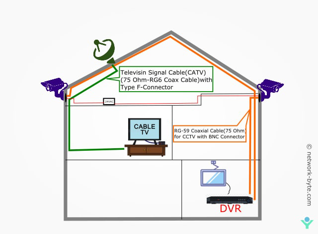
If your equipment has frequency ratings (above 50 MHz) Use RG 6 Coax Cable.If frequencies are lower than that, then use RG 59.
10Broad36– It is an obsolete computer network standard in the Ethernet family. The standard supports 10 Mbit/s Ethernet signals over standard 75-ohm cable television (CATV) cable over a 3600-meter range. Broadband provides advantages over the baseband signal that multiple signals can be carried on the same cable in Broadband.
Difference Between RG-59 and RG-6 Coaxial Cables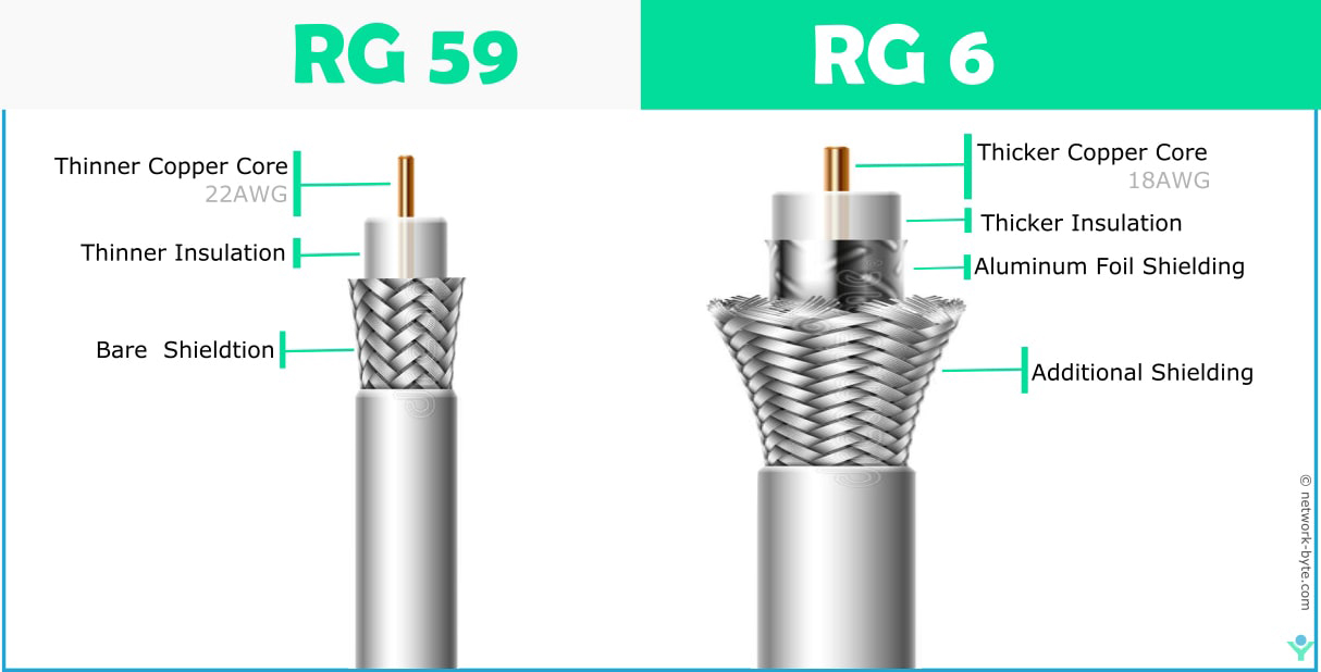
Twisted Pair
Twisted pair cable is the most common type of network medium used in LANs today. A transmission media consists of color-coded pairs of two shielded or unshielded insulated copper wires which are arranged in a spiral pattern. The spiral pattern is an important aspect of twisted-pair cables in order to minimize crosstalk or interference between adjoining wires. The advantage of using a twisted pair cable are:
- It is lighter, thinner and more flexible
- Easy to install
- It is inexpensive
Twisted pair are twisted together for the purposes of canceling out electromagnetic interference (EMI) from external sources and crosstalk between neighboring pairs.
The twisted pair cable is most often implemented in star topology. It can handle the faster networking transmission rates. The major disadvantage of twisted pair is because of its flexibility, it is more prone to physical damage. Therefore it is ideal in offices or work groups that are free of electromagnetic interference. There are two varieties of twisted pair cabling ,they are:
- Unshielded Twisted Pair (UTP)
- Shielded Twisted Pair (STP)

Unshielded Twisted Pair (UTP)
Unshielded Twisted Pair (UTP) 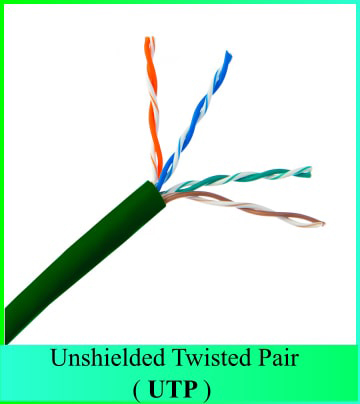 cabling consists of two unshielded wires twisted around each other that contain no shielding. It is commonly used in telephone wires and is common for computer networking because of the high flexibility of the cables. It is a plastic connector that looks like a large telephone-style connector. The standard connector for unshielded twisted pair cable is RJ-45 connector.
UTP has Six categories of cable standards defined by the Electronic Industries Association and Telecommunications Industry Association (Commonly Known as EIA/TIA). The six categories of unshielded twisted pair are:
Categories of Unshielded Twisted Pair
In order to manage the network cabling, you need to be familiar with the standards that may be used on modern networks. The categories of unshielded twisted pair cable are described below.
Category 1
- It is a form of UTP that contains two Pairs of wire
- Cat 1 is suitable for voice communications but not for data.
- It can carry up to 128 kilobits per second (Kbps) of data
- It is usually used for telephone wire Data rate – 1 Mbps. This type of wire is not capable of supporting computer network traffic and is not twisted.
Category 2
- It contains four wire pairs and can carry up to 4 Mbps to data.
- Cat 2 is rarely found on modern networks.
- Category 2 or CAT 2 is capable of transmitting data at up to 4 Mbps. This type of cable is seldom used.
Category 3
- Cat 3 is made up of four twisted-pair wires;Each twist is three times per foot.It is certified to transmit data up to 10 Mbps
- Cat 3 has typically been used for 10 Mbps Ethernet or 4 Mbps Token Ring network.
- The Cat 3 cabling is gradually replaced with Cat 5 to accommodate higher throughghput.
Category 4
- Cat 4 is made up of four twisted-pair wires, specialized to transmit data up to 16 Mbps and is rarely used in new installations.
- Cat 4 may used for 16 Mbps Token Ring or 10Mbps Ethernet networks.It is guaranteed for signals as high as 20 MHz and provides more protection against crosstalk and attenuation than Cat 1, Cat 2, or Cat 3
Category 5
- Cat5 is the most popular twisted pair Ethernet cabling designed for high signal integrity which is in common use today.
- Cat5 contains four wire pairs and supports up to 100 Mbps throughput
- It is the most popular form of UTP for new network installations and upgradeds to Fast Ethernet.
- In addition to 100 Mbps Ethernet,Cat5 wiring can support other fast networking technologies.
- It is popular because it is both affordable and high-speed for today’s local area networks.Cat 5 cables are often used in structured cabling for computer networks such as fast Ethernet.
Category 5e
- Category 5e (CAT5e) cable, also known as Enhanced Category 5, provides improved crosstalk specification.
- it to support speeds of up to 1000Mbps (Gigabit Ethernet) 1Gbps
- It contains four pair of twisted wire.
- The Cat 5e standard provides performance of up to 100 MHz and can be used up to a maximum length of 100 meters.
- Cat 5e is distinguished from the original Cat 5 standard primarily in its performance.
- Specifications in Cat 5e including Near-End Crosstalk (NEXT), Power Sum Equal-Level Far-End Crosstalk (PS-ELFEXT), attenuation and return loss(RL)
- It is backward compatible with the Cat 3 and Cat 5 cable standards.
- CAT5, CAT5e is a 100-MHz standard, but it has the capacity to handle bandwidth superior to that of CAT5.
Category 6
- Cat6 cable was originally design to support Gigabit Ethernet .It is similar to Cat5 wire, but contain a physical separator between the four twisted copper wire pairs to reduce the electromagnetic interference.
- Cat 6 cables consist of four unshielded twisted pairs (UTP) of copper wire terminated by RJ45 connectors.
- it support a speed of 1000BASE-T (Gigabit Ethernet, or GbE) maximum distance of 100m and speed 10GBASE-T (10-Gigabit Ethernet, or 10 GbE) achievable when reducing cable lengths to less than or equal to 50 meters.
- 10-Gigabit Ethernet speeds are The Cat 6 standard provides performance of up to 250 MHz bandwidth.
Shielded Twisted Pair (STP)
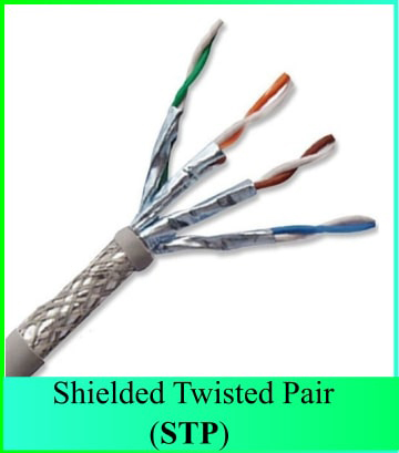 Shielded Twisted-Pair cabling is usually used in several network types. STP cable usually contains four pairs of twisted copper wires. It is different from UTP in the twisted pairs and is in a shield with electrically grounded woven copper mesh separating them from the cable’s outer sheath. This is done for the purpose of preventing interference via three techniques: shielding, cancellation, and wire twisting. It is suitable for environments with electrical interference. The essence of the shielding is to provide resistance to external Electromagnetic Interference(EMI) and to prevent crosstalk. STP is considered to be more secure than UTP, because of its shielding. It is however more expensive than UTP.
ISO/IEC11801 Cabling Acronym
The Code before the Slash Designates the shielding for the overall cable itself, While the code after the slash determines the shielding for the individual Pairs and TP is for Twisted Pairs.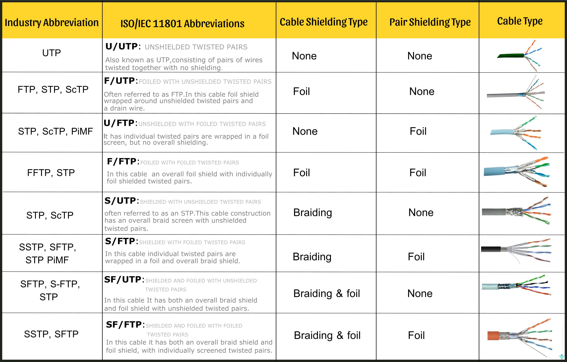
Category 6a
- Category 6a (CAT6a), also known as Augmented Category 6.
- It is mostly used in Server farms, storage area networks, data centers, and riser backbones are common 10G/Cat6a applications.
- It has additional and tighter twists, also often shielded to reduce crosstalk.
- CAT6A is capable of supporting data transfer rates of up to 10Gbps at a distance of 100 meters.
- Cat6a doubles data transmission bandwidth, from 250MHz (in Cat6) to 500MHz.
- CAT6a provides enhanced performance for Power over Ethernet (PoE)
Category 7
- Cat 7 also known as a shielded version of Cat6a each twisted wire pairs to be fully shielded for higher performance than preceding Ethernet.
- It is shielded with Screen Shielded Twisted Pair (SSTP) or Screened Foiled Twisted Pair (SFTP) wiring, which almost completely eliminates alien crosstalk while significantly improving noise resistance
- Cat 7 standard provides a maximum bandwidth of 600 MHz used up to a maximum length of 100 meters at speed of 10Gbps
- Cat7 cable is commonly terminated using a GG45 connector, which is a connector that is backward compatible with the 8p8c RJ45 connectors used on Cat6 or Cat5e cable.
Category 7a
- Category 7a (CAT7a), also known as Augmented Category 7.
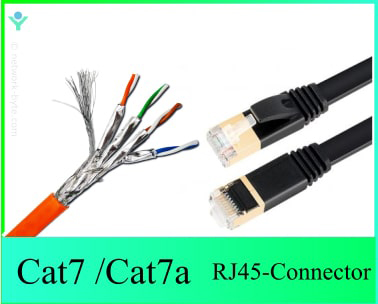
- Category 7a cable has conductor pairs that are individually wrapped in foil and surrounded by an overall braid.
- Category 7a (Cat7a) support data speed 10-gigabit Ethernet with bandwidth 1,000 MHZ
- CAT7a is designated S/FTP: Shielded, Foiled Twisted Pair. each twisted pair individually foiled, the four sets are then wrapped in an additional braided shield.
- CAT7a shielding needs to be grounded, and GigaGate45 (GG45) or TERA connectors are used. TERA connector is not compatible with a standard 8p8c (RJ45) connector.
Category 7 and 7a are not recognized by the TIA/EIA

The GG45 connector has four additional conductors that provide support for frequencies of up to 600MHz, and up to 1000MHz using Cat7a.
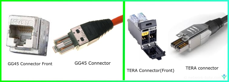
Cat7 and cat7a cable may also be terminated using TERA connectors, which were developed by Siemon™. The TERA connector has a unique footprint and is not compatible with a standard 8p8c (RJ45) connector
Category 8
- Category8 (CAT 8 )is capable of supporting bandwidths of up to 2 GHz (2000 MHz) for up to 30 meters of cabling.
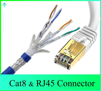
- It is ideal for use where the distances between units are short. In datacenter switch-to-server connections
- Data Speed supported by Cat8 from 25/40GBASE-T Gigabit Ethernet -25 Gbps (Cat8.1) to 40 Gbps (Cat8.2)
- Cat8 still terminated in RJ45 connections. It is backward compatible with previous Category standards.
- Cat8 designed only for data centers where distances between switches and servers are short. These cables are shielded (F/UTP, S/FTP or U/FTP)

Compression UTP vs STP cable
FIBER OPTIC CABLE
The world of telecommunications is rapidly moving from copper wire networks to fiber optics due to higher capacity bandwidth in fiber Optic cable. fiber optics are now in widespread use, and form the backbone of most telecommunications networks.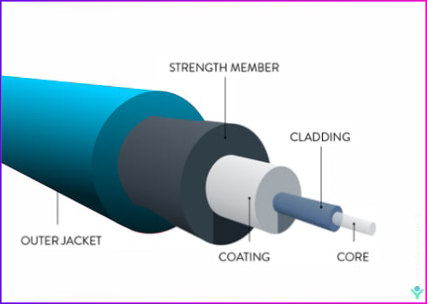
Fiber-optic cabling contains long thin strands of pure glass or plastic fiber.
Fiber optic cable is composed of two layers of glass: The core, which carries the actual light signal, and the cladding, which is a layer of glass surrounding the core. The cladding has a lower refractive index than the core. This causes Total Internal Reflection within the core.
The fiber is coated with a protective plastic covering called the “primary buffer coating” that protects it from moisture and other damage.
TOTAL INTERNAL REFLECTION states that when the angle of incidence exceeds a critical value, light cannot get out of the glass; instead, the light bounces back in.
Optical Transmission that electromagnetic radiation, typically infrared light, along a silica or glass-based medium by the process of reflection and refraction.
Why use optic fiber cable?
- signals can be transmitted to a longer distance than copper cables.
- It has high carrying capacity (Extremely High Bandwidth:, THz or Tbits/s)
- They have very low transmission losses (<0.2dB/km, cf1dB/km microwave, 10db/km twisted copper pair).
- They do not dissipate heat.
- They are immune to cross-talk and electromagnetic interference. Fiber optic transmission is virtually noise free.
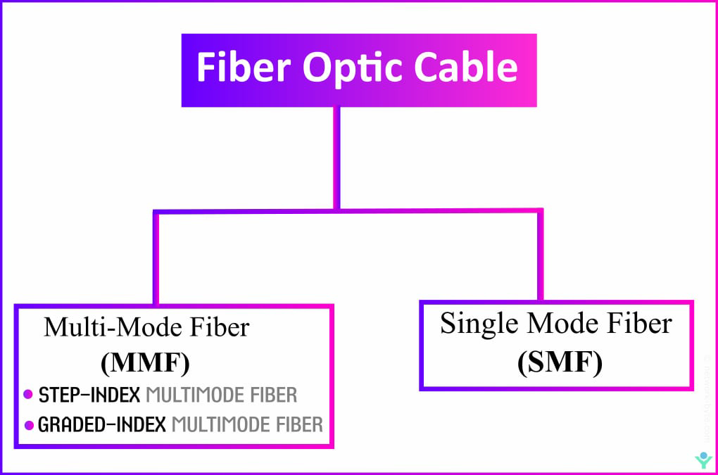
Optical fiber types
Based on the Light travel through one Path(that is mono mode or single mode fiber) or more than one path(that is called multi mode fiber) along with core diameter fiber optic cable are divided into two major categories.
- Multimode(MM) fiber optic cable
- Single Mode(SM) fiber optic cable
Multimode(MM) fiber optic cable
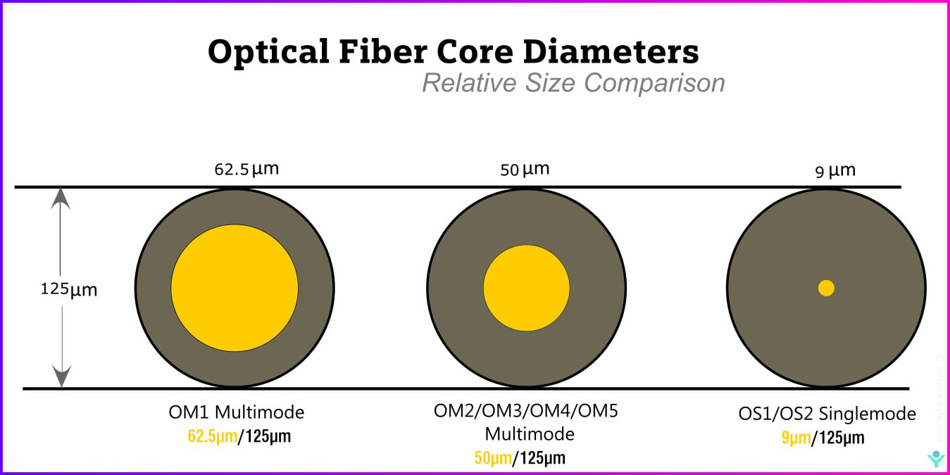
Fibers that carry more than one mode are called multimode fibers. Multimode(MM) fiber optic cable has a fairly large core diameter that enables multiple light modes to be propagated. Multimode fibers have a much larger core diameter. Two types of Multimode cables with core diameters of 50 micron and 62.5 micron are specified.
Multimode fiber optic cables can handle high bandwidth and faster transmissions but only over short distances.
Transceiver-(Transmitter+Reciver) Electronic device that both transmits and receives analog or digital signals.
Multimode fiber generally used with light Emitting diodes(LEDs) and vertical-cavity surface-emitting lasers (VCSELs) operating wavelength at 850 nm and 1300 nm.
Multi-mode fibers are described by their core and cladding diameters. Thus, 50/125 μm multi-mode fiber has a core size of 50 micrometres (μm) and a cladding diameter of 125 μm.
There are two types of multimode fibers. One type is step-index multimode fiber and the other type is graded-index multimode fiber.
STEP-INDEX MULTIMODE FIBER
The transition between the core and cladding can be sharp, which is called a step-index profile, or the refractive index of the core is uniform throughout and undergoes an abrupt change at the core-cladding boundary.
Step-index multimode fibers are mostly used for imaging and illumination.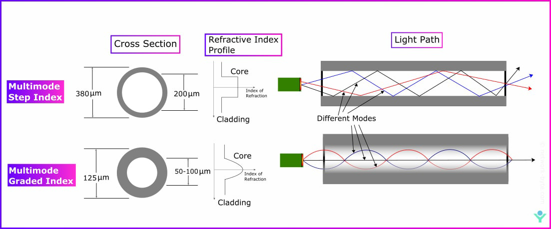
GRADED-INDEX MULTIMODE FIBER
The refractive index is maximum at the center of the core then it decreases towards the core-cladding interface.
The change in refractive index causes refraction, instead of total internal reflection. No total internal reflection happens because refraction bends light rays back into the fiber axis before they reach the cladding boundary.
Technical naming conventions In ISO/IEC 11801 and EIA/TIA standards and specifications for Multimode Fiber
Multimode fiber cable is prefixed with ‘OM’ –Optical Multimode. In this cabling standards deal with cable and connecting hardware.
Types of Multimode Fiber Cable and Specifications
OM1
- Core Size – 62.5µm
- Jacket Color – Orange
- Data Rate – 10Mbps-1Gbps
- Wavelength – 850nm
- Distance – Up to 300 meters
- Application –Local Area Networks(LANs) deployed in premises application.
OM2
- Core Size – 50µm
- Jacket Color – Orange
- Data Rate – 1Gbps
- Wavelength – 850nm
- Distance – Up to 600 meters
- Application –Local Area Networks(LANs) & deployed in premises applications Generally used for shorter distances. Has twice the distance capacity has OM1
OM3
- Laser Optimized Multimode Fiber(LOMMF)
- Core Size – 50µm
- Jacket Color – Aqua
- Data Rate – 10Gbps
- Wavelength – 850nm VCSELS(Vertical-Cavity Surface Emitting Lasers)

- Distance – Up to 300 meters
- Uses fewer modes of light, enabling increased speeds
- Data Capacity rate 40GB or 100GB up to 100 meters utilizing an MPO connector
- Application – Local Area Networks(LANs) , Larger Private Networks
OM4
- Laser Optimized Multimode Fiber(LOMMF)
- Core Size – 50µm
- Jacket Color – Aqua
- Data Rate – 10Gps
- Wavelength – 850 nm and 1300 nm
- Distance – Up to 550 meters
- Data Capacity rate 100GB up to 150 meters utilizing an MPO connector
- Application – High-Speed Networks, Data Centers, Corporate Campuses
OM5
- Also known as WBMMF (wideband multimode fiber) newest type of multimode fiber
- Core Size – 50µm
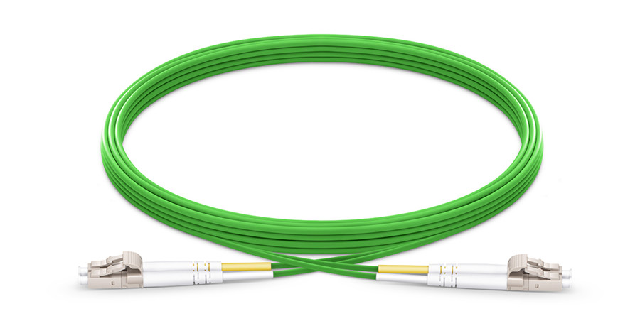
- Jacket Color – Lime Green
- Fully compatible and can mate with OM3 and OM4 cabling
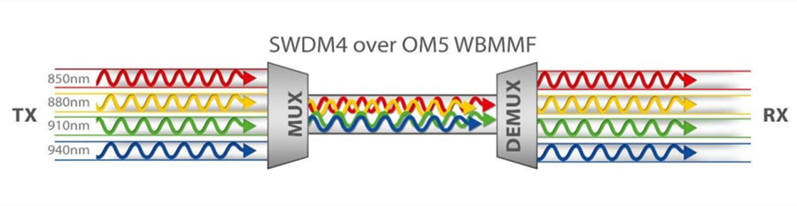
- Utilizes a wider range of wavelengths between 850nm and 953nm
- Support four Short Wavelength Division Multiplexing (SWDM) channels, each carrying 25G of data to deliver 100G Ethernet using a single pair of multimode fibers.
- Designed for 40Gb/s, and 100Gb/s transmission which reduces the fiber counts for high speed transmissions.
- Application – Multiple enterprise environments, from campuses to buildings to data centers that require greater link distances and higher speeds.
Single Mode(SM) fiber optic cable
single-mode optical fiber (SMF) (also called monomode fibers) is an optical fiber that carry only a single mode of light. single-mode optical fiber has a core diameter between 8 and 10.5 µm and a cladding diameter of 125 µm.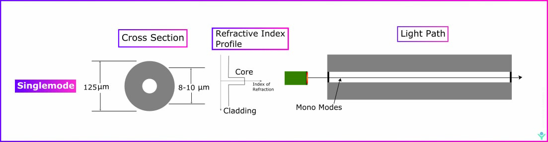
Technical naming conventions In ISO/IEC 11801 and EIA/TIA standards and specifications for Singlemode Fiber.
Singlemode fiber cable is prefixed with ‘OS’ –Optical Single mode.In this cabling standards deal with cable and connecting hardware.
Types of Single Mode Fiber Cable and Specifications
OS1
- Core Size – 9µm

- Jacket Color – yellow for jumpers but uses variety of colors depending on the application and the outer jacket type
- Data Rate – 10Gps
- Wavelength – 1310 nm and 1550 nm
- Distance – Up to 2,000 meters
- cable construction – Tight buffered construction
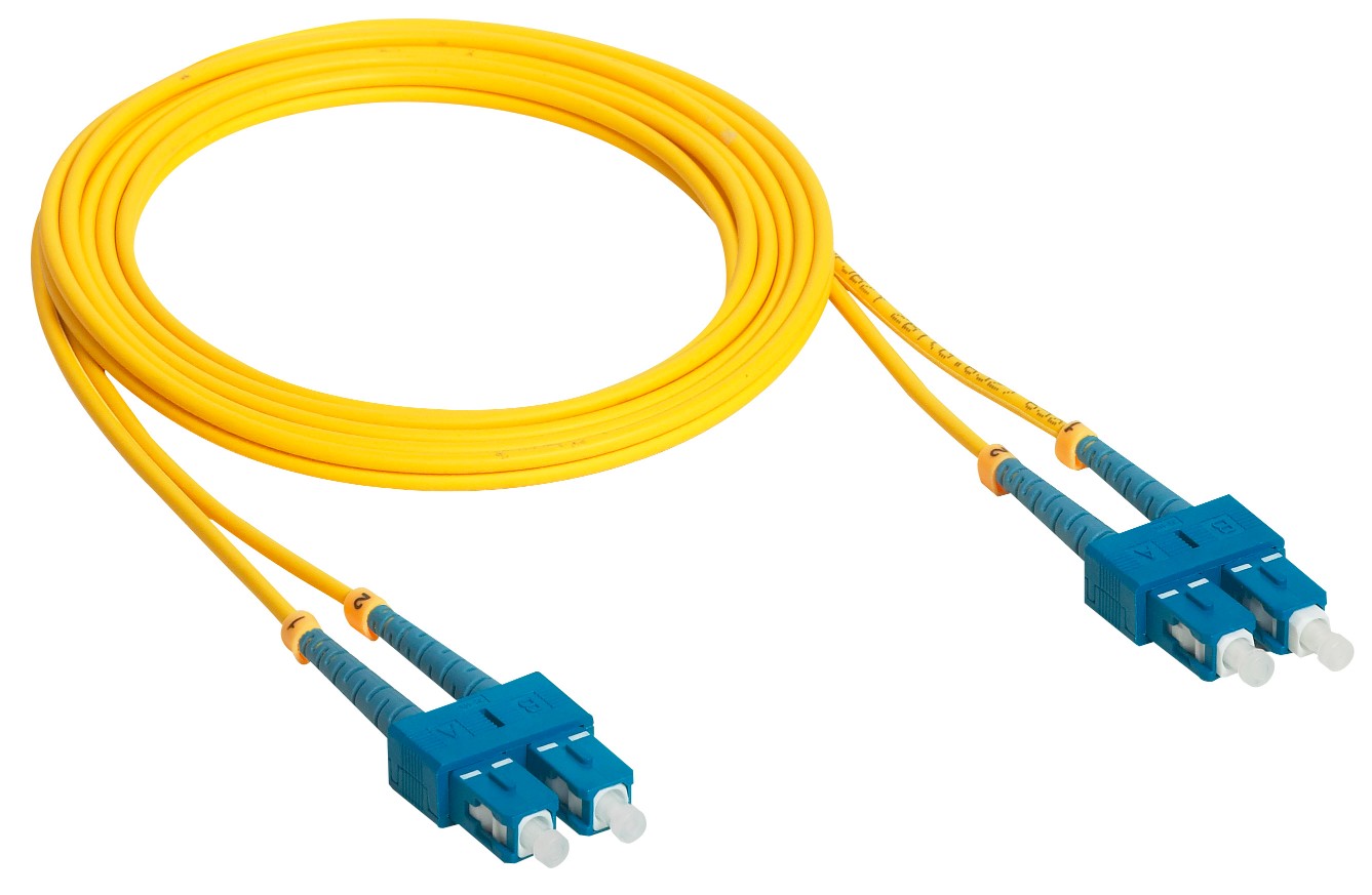
- Application – designed for premises , Indoor Use, moderate distance telco local loops, LANs and point-to-point links in cities, buildings, factories.
OS2
- Core Size – 9µm
- Jacket Color – yellow for jumpers but uses variety of colors depending on the application and the outer jacket type
- Data Rate – 10Gps

- Wavelength – 1310 nm and 1550 nm
- Distance – 5,000 to 10,000 meters
- cable construction – loose tube or blown cable construction
- Application – designed for premises , Outdoor r Use, long distance telco backbone, LANs and point-to-point links in cities, buildings, factories.OS2 can support speeds up to 100G and distances up to 200km (124 miles).
The main difference between single mode OS1 and OS2 is cable construction rather than optical specifications.
Manufactures also make fiber in non-standard color coding. For outside plant cables, the standard jacket color is black.
Connection of fiber cables
The two major technique used for connection (Splicing) for two fiber optic cable are
Fusion Splice Joints 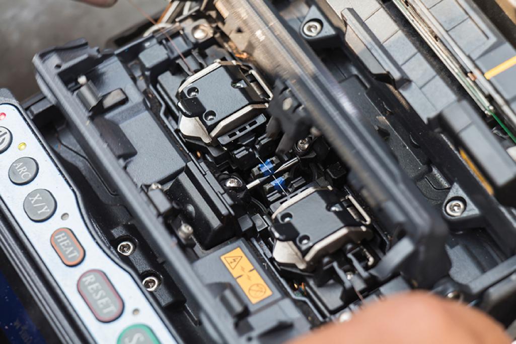 -The purpose of a fusion splice joints is to literally weld prepared fiber ends together, thereby creating a permanent(non-demountable) joint featuring the minimum possible optical attenuation(and no reflection).
Mechanical splicing is an alternative to fusion splicing and uses a simple but high-quality alignment mechanism which enables the positioning and subsequent fixing of the two fiber ends by use of crimps or glue.
Cable Jacket Material
While selecting fiber optic cable consider the jacket type is very important it provide environmental protection .Many different materials are available for cable jacketing some of the more popular jacketing materials used for optical cables.
Fire Rating for Fiber Optic Cable
The National Electrical Code (NEC) specified fire resistance for both non-conductive and conductive cables based on the use in plenum ,riser, and general Purpose areas.
Plenum area-It is Space in building where ventilation or air distribution system in drop Ceiling and raised floors.
Riser area – It is area between floor where shaft or duct that runs vertically through floor.
general-purpose area-It is area excluding Plenum and riser.
Types of Unguided media
Unguided Transmission is also known as Unbounded Transmission where Data signal are not bonded to cable media. In Unguided media signal are transmitted as electromagnetic signal through air. This transmission uses different kinds of waves like radiowaves, microwaves, infrared waves.
Unguided signals can travel from the source to the destination in several ways: Gound propagation, Sky propagation and Line-of-sight propagation
Radio Waves
Radio waves are EM(Electromagnetic)Waves that have wavelength between 1 millimetre to 100 kilometres(300 Ghz to 3Khz) in frequency.
Radio waves are generated by radio transmitters and received by radio receivers. Radio stations transmit radio waves using transmitters,Which are received by the receiver installed in our devices.Both transmitters and receivers use antennas to radiate or capture radio signals.
Radio waves are omni directional means they travel in all the direction from the source. When an antenna transmits radio waves, they are propagated in all direction. A sending antenna send waves that can be received by any receiving antenna. It issued Mobile, AM/FM radio,television.
Micro Waves
It is a line of sight transmission i.e. the sending and receiving antennas need to be properly aligned with each other. Microwaves are a type of radio waves with high frequencies. The frequency of microwaves lies in the 300Mhz to 300Ghz.
Microwaves are widely used for point-to-point communication because their small wavelength, Which means that the signal is focused into a narrow beam. Additionally, each antenna must be within line of sight of the next antenna.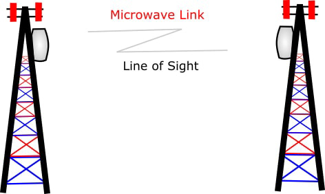
Microwaves have higher frequencies and don’t penetrate wall like obstacles.
It is used for satellite communication,navigation,radar,remote sensing and other short distance communication system.
Microwaves, due to their unidirectional properties, are very useful when unicast(one-to-one) communication is needed between the sender and the receiver. They are used in cellular phones, satellite networks and wireless LANs.
Infrared
Infrared signal have frequencies between 300GHz to 400THz.They are used for short-range communication.
Infrared waves having high frequencies prevents interference between one system to another. In addition, we cannot use infrared waves outside a building because the sun’s rays contain infrared waves that can interfere with the communication.
Infrared signals can be used for short-range communication in a closed area using line-of-sight propagation. Infraed waves are used for very short distance communication like TV remote,Wireless speakers,automatic doors,infrared thermometer or IR thermometer.


Great article on media types! I found it really helpful in understanding the differences between them. As a web developer, I often find myself struggling to choose the right media type for a particular task. This post has clarified things for me and I feel more confident in my ability to make informed decisions. Thanks for sharing!